Making cost-effective designs has become a basic requirement in manufacturing, and proper nesting can contribute to this overall goal.
Material and manufacturing costs are two major elements that influence total product cost. Through thoughtful design, both costs can be controlled or limited at the early design stage itself.
 In sheet metal manufacturing, nesting commonly is used to fit multiple 2-D shapes on a larger sheet for optimal material utilization. Automatic nesting software generally is used in the manufacturing stage for cutting blanks of multiple components from standard sheet sizes. In spite of using automated nesting, the manufacturing engineer is constrained in his or her effort to optimize material utilization with the existing design. By the time that design reaches the manufacturing stage, it’s frozen. Design changes are unlikely.
If nesting is carried out at the design stage, however, the manufacturing engineer has a better chance to optimize material usage. Currently nesting is thought of as a manufacturing activity. To get maximum benefits in material cost reduction, nesting should be a part of the design process itself.
A recent study shows that most young design engineers don’t have a lot of manufacturing knowledge, and as a result, their designs generally are not cost-effective in terms of manufacturing. On the other hand, expert designers with thorough manufacturing knowledge generally ensure that their designs produce minimal scrap and achieve 90 percent-plus material utilization. The cost of raw material to scrap is 1-to-10, which means that if a sheet is procured at $100 per pound, the scrap will be worth only $10 per pound, which doesn’t even take into account additional expense and hassles associated with inventory management issues.
So, to ensure that both senior and junior design engineers produce cost-effective designs, some companies have started using automated nesting technology at the design stage as an aid for all of their designers. It gives the designers the ability to understand how parts will be laid out and what the approximate cost will be.
Rules for Product Cost Reduction
Several general guidelines should be followed for effective material utilization and cost reduction:
- Design parts as near rectangle as possible.
- Designs pair of parts as near rectangle as possible.
- Design maximum part length and width as fraction multiples of sheet length and width.
- Analyze opportunities to improve material utilization by redesign.
- Choose the right sheet size from multiple standard sheet sizes.
The following examples have been made very simple for ease of understanding.
Design Parts as Near Rectangle as Possible.
 Fig 1
Fig 1
The original design of this electrical cabinet assembly consists of two sheet metal parts as shown in Figure 1, out of which Part A is rectangular in shape in the flat state and Part B is T-shaped.
 Fig 2
Fig 2
Since the flat pattern of Part B is non rectangular in shape, it is redesigned into two parts, Part B1 and Part B2, as shown in Figure 2. Nested layouts and the remnants are shown in Figure 3 for both the original assembly and the redesigned assembly. It can be clearly seen that for the redesigned assembly, the scrap area, shaded in gray, is less and the remnant area, shaded in pink, is more.
 Fig 3
Fig 3
Weight savings that result from the redesign are shown in Figure 4. The two redesigned assemblies weigh 10.1 lbs. less than the original designs. With a production rate of 10 assemblies per day and 200 days per year, the manufacturer would not need to buy 10.1 lbs. of material because of the redesigned assembly.
 Fig 4
Fig 4
In this case, it should be noted that the part design was such that it could be redesigned—splitting the one part into two without affecting the functionality of the part. Because the part is split, additional welding and assembly operations are needed, but the additional cost added by splitting the part is likely to be less than the cost benefits achieved through better material utilization.
Design Pair of Parts as Near Rectangle as Possible
It is not always possible to design parts in near-rectangular shape, but if it is possible, the effort could lead to better nesting.
 |
 |
| Fig 5a | Fig 5b |
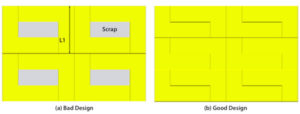
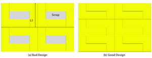
For example, Figure 5a shows a nested layout of an L-shaped part. Even though a pair of parts forms a rectangle, it generates scrap. By adjusting the arm-length dimension L1, scrap is avoided as shown Figure 5b. Moreover, the redesign has improved utilization, creating a 12‐part nest instead of the eight‐part nest.
Design Maximum Part Length and Width as Fraction Multiples of Sheet Length and Width
While designing parts, it is always cost-effective to design the maximum length and width to suit standard sheet sizes.
 |
 |
| Fig 6a | Fig 6b |
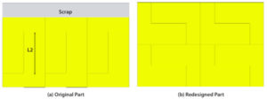
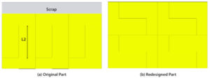
In this example, the nested layout of a part, shown in Figure 6a, generated scrap. On re-examining the design, the design engineer found that the length L2 can be modified, and the length is redesigned to suit the sheet as shown in Figure 6b. Material utilization improved from a six‐part nest to an eight‐part nest by this simple modification.
Analyze Opportunities to Improve Material Utilization by Redesign.
Because material cost is a major share of product cost in sheet metal products, engineers need to design parts or assemblies so that at least 90 percent of the sheet is used. All opportunities that could result in improved material utilization have to be analyzed.
 |
 |
| Fig 7a | Fig 7b |
In a worktable design in the woodworking industry, the original design results in poor material utilization (64.83 percent) as shown in Figure 7a. As part of a redesign of the model, a fillet is added in a corner as shown in Figure 7b, which doesn’t affect the functionality of the part. Because of this change, material utilization improved from a four‐part nest to a six‐part nest, greatly increasing material utilization of the sheet to 95.96 percent.
 |
 |
| Fig 8a | Fig 8b |
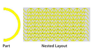
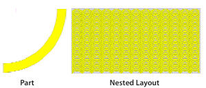
Another interesting case shown in Figure 8a delivers a utilization rate of 39.58 percent. Engineers redesigned the part into two pieces as shown in Figure 8b; two of the parts can be welded together to form the original design. This improves the material utilization of the sheet to 75.03 percent.
Though utilization of 90 percent is not achieved because of design limitations, redesign helps to generate 273 pairs of the redesigned model, compared to 144 of the original models. Welding is an additional process introduced by redesign, but it is found that material savings are greater than the additional costs of welding and cutting.
Choose the Right Sheet Size From Multiple Standard Sheet Sizes.
Standard sheet sizes—like 4 by 8 ft., 5 by 8 ft., 6 by 8 ft., 7 by 8 ft., 8 by 8 ft., 10 by 8 ft., 4 by 10 ft., 5 by 10 ft., 6 by 10 ft., 7 by 10 ft., 8 by 10 ft., 10 by 10 ft., 4 by 12 ft., 5 by 12 ft., 6 by 12 ft., 7 by 12 ft., 8 by 12 ft., 10 by 12 ft.—are commonly available in the market. That provides quite a variety to choose from if an operator is making the choice and could end up driving manufacturing engineers crazy. Simply put, material utilization for the same set of parts on different sheet sizes is not the same.
Generally, contract manufacturers decide sheet sizes based on the machine specifications available in the machine shop, along with their availability and cost. Companies that outsource manufacturing have to either choose from standard sheet sizes or live with specific sheet sizes based on the vendor’s machine specifications. Choosing the wrong sheet size can have an adverse effect on product cost.
For example, material utilization for manufacturing six simple components requires three sheets of 6 by 8 ft., but requires only two sheets of 4- by 12-ft. sheets as shown in Figure 9. For just six components, a weight savings of 224.9 lbs. is achieved for a sheet thickness of 0.118 in.
 Fig 9
Fig 9
This example is a very simple case. For assemblies containing multiple parts, choosing the right sheet size becomes crucial.
Start Following the Rules Early
It is generally agreed that a major portion of product cost is decided before manufacturing. To reduce product cost, engineers need to explore multiple possibilities for cost reduction early in the design stage.
Guidelines for promoting effective material utilization and cost reduction have been around for a long time, but actually putting these recommendations into effect does not always happen because of practical difficulties related to the need to analyze multiple possibilities. In reality, very few experienced designers have attained expertise in designing such cost-effective designs.
With the use of nesting software integrated in CAD modelers, however, analyzing all such cost-reduction possibilities becomes viable. Design for nesting as part of the design for the manufacturing process becomes possible, and organizations can reap considerable benefits.

